Sensors are sophisticated devices, modules or subsystems that are frequently used to detect and respond to electrical or optical signals. However, in today’s technology, shunt-based current measurements are getting widely known as an alternative to sensors for controlling and monitoring circuits. Thus, to make these measurements correctly, it is important to understand how these shunts work.
Understanding How Shunts Work
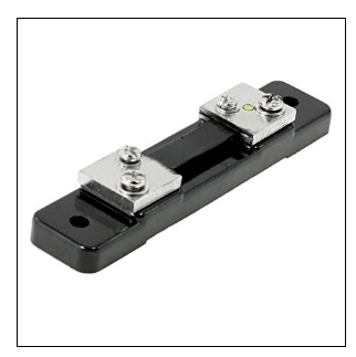
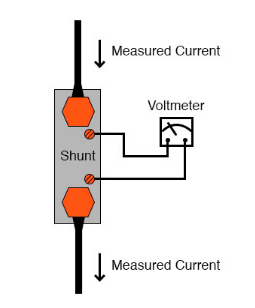
A shunt, also known as a current shunt resistor, is a low-value resistor used to measure current. The shunt is usually connected to a series which carries the current to be measured. A measurement device is then connected to the shunt. It will measure the voltage drop generated from the current through the shunt. This value is best described through the Ohm’s law (I = V/R), where R is the resistance, V is voltage and I is the current.
This method is typically used for safety applications because it allows for easy detection and elimination of faults. It is also known for its accuracy in measurement which results in the efficient control of drives or monitoring of battery management. But because shunt resistors are more expensive than other resistor technologies, they are available in smaller batch sizes and test samples. Nevertheless, shunt resistors are still excellent value for money.
Shunts are can be used for a direct measuring application or alternating current. Due to the increasing number of condition measurement in vehicles, shunts are currently expanding its exposure. Some of these systems with shunts are engine and battery management, airbag control units, ABS, and infotainment systems,.
Current-sense resistors are also becoming ever more widely used for industrial applications, medical technology, for regenerative energies, and for smart metering. Most popular are those smaller shunts with higher outputs and those custom-made versions specific to special shapes and sizes ordered.
Selecting Resistors That Will Accurately Gauge Current
Layer resistors are less expensive but their resistance value adapts with temperature to a higher degree than those full-metal devices. Its formation also poses a disadvantage. With metal layer resistors, a paste is applied to a ceramic substrate and adjusted to the desired value using laser trimming. This results in an inhomogeneous structure that is trimmed to the rated value as a meandering shape. This meandering shape, then, causes a series of inductance, which results in degrading current measurements. Therefore, these kinds of resistors are should only be considered if inductance is irrelevant.
On the other hand, to prevent additional inductance to develop, full-metal shunt resistors are made with a homogeneous resistive element. This quality is important to those high-precision applications as medical technology or precision measurement devices. In addition, these resistors are quite known for its high measurement accuracy and resistance to thermal shock. They are, in fact, available in different sizes – some are even much larger than standard chip resistors. Full-metal resistors can operate with an output of up to 7 W at maximum temperatures of 275°C. They can have resistive values up to the low single-digit milliohm range.
Described here is the formula used to determine the optimum resistive value: The lowest measuring voltage that still gives sufficiently accurate results is divided by the lowest current value of the measuring range.
Other shunts consist of four wires. With this, the current flows through two connections and the voltage drop is measured at the other two. Measuring errors is more likely possible, but these errors can easily be eliminated through the internal Kelvin connections, which is used to determine the voltage drop at the resistors. These four-wire shunts are used when the line and contact resistance are relatively high and, in contrast to the measured resistance, not negligible. Also when the resistive value is below 10 mΩ. When the resistive values of the conductors are also in the milliohm range, they must also be considered.


